Case studies
X-ray computed tomography for assessing metal components 3D printed in µ-gravity
As humanity contemplates manned missions to Mars, strategies need to be developed for the design and operation of hospitable environments to safely work in space for years. The supply of spare parts for repair and replacement of lost equipment will be one key need, but in-space manufacturing remains the only option for a timely supply. With high flexibility in design and the ability to manufacture ready-to-use components directly from a computer-aided model, additive manufacturing (AM) technologies appear extremely attractive. For the manufacturing of metal parts, laser-beam melting is the most widely used AM process.
The challenge is how to manipulate powder materials and deposit stable powder layers in the absence of gravity, as layer formation in powder-based additive manufacturing is generally governed by gravitational forces:
1. gravitation directs the powder flow and enables a certain degree of compaction.
2. gravitation stabilises the powder bed and prevents the powder particles from leaving the building unit.
In this work, a method to stabilize powder layers by establishing a gas flow throughout the powder bed is proposed and has been tested in three DLR’s (Deutsches Zentrum für Luft-und Raumfahrt) parabolic flight campaigns. The so-called gas flow-assisted powder deposition is based on a porous building platform acting as a filter for the fixation of metal particles in a gas flow, which is driven by a reduced pressure established by a vacuum pump underneath the platform. The gas flow established by means of a vacuum pump throughout the powder bed imposes a drag force on the particles, which in average is directed toward the porous building platform, that is, in the direction in which the gravitational force would normally act. This force can stabilize the powder bed even when the gravitational force is absent.
Using this platform, the worldwide first metallic tool, a 12 mm wrench has been manufactured by LBM under μ-g conditions. Moreover, other parts have been manufactured at different accelerations provided by a parabolic flight, that is, hyper gravity (1.8 g), μ-g (<0.01 g), and 1 g. In a first survey of the parts microstructure, no significant deviations from a part manufactured at 1 g conditions have been found. X-ray computed tomography scanning also did not reveal any major defect within the part. Hence, the current work has presented the first results on the feasibility of an LBM process for additively manufactured ready to use metal parts in space.
Andrea Zocca and Jens Günster, Bundesanstalt für Materialforschung und-prüfung (BAM), Berlin, Germany
Impact damage characterisation in composite panels by X-ray computed tomography
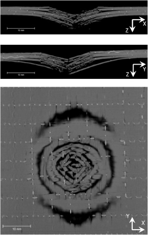
One of the great strengths of X-ray computed tomography over conventional inspection methods (ultrasound, thermography, radiography) is that it can image damage in 3D. However, for curved or deformed composite panels it can be difficult to automatically ascribe the damage to specific plies or inter-ply interfaces (Fig 1).
An X-ray computed tomography (CT) data processing methodology has been developed to extract the through-thickness distribution of damage in curved or deformed composite panels. The method was applied to [(0°/90°)2]s carbon fibre reinforced polymer (CFRP) panels subjected low velocity impact damage (5 J up to 20 J) providing 3D ply-by-ply damage visualisation and analysis.
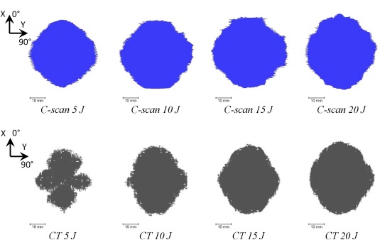
An X-ray computed tomography (CT) data processing methodology has been developed to extract the through-thickness distribution of damage in curved or deformed composite panels.
The method was applied to [(0°/90°)2]s carbon fibre reinforced polymer (CFRP) panels subjected low velocity impact damage (5 J up to 20 J) providing 3D ply-by-ply damage visualisation and analysis.
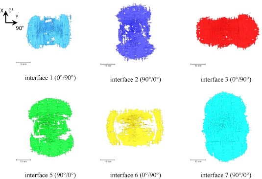
The distance transform approach allows slices to be taken that approximately follow the composite curvature allowing the impact damage to be separated, visualised and quantified in 3D on a ply-by-ply basis.
In this way the interply delaminations have been mapped, showing characteristic peanut shaped delaminations with the major axis oriented with the fibres in the ply below the interface.
This registry to the profile of the panel constitutes a significant improvement in our ability to characterise impact damage in composite laminates and extract relevant measurements from X-ray CT datasets.
Jasmin Stein - The Welding Institute Cambridge.